| < PREVIOUS - WORK IN PROGRESS |
Modelling
One of the tedious and time consuming part when creating pictures is modeling. But ... you need to do it ... empty scene is not very interesting for the viewer. ;) So let's go and see what I have done in this scene when it comes to modelling. First, I will list the tools I use often. The detailed explanation of those tools can be found maya manuals. It is best to create empty scene and test these tools until the moment when you are familiar with them. Remember that you need a lot of hours working with basic Maya tools before you have enough practice to take the next step and create a little more complicated stuff.
Just to give you a short list of the tools I use very often when modeling: Create menu: Nurbs stuff: sphere, cylinder, plane, circle ... Polygon stuff: sphere, cube, cylinder, plane, CP Curve Tool, Edit Curves menu: Attach and Detach curves, Open/Close curves, Cut curve, Curve Fillet, Rebuild Curve, Surfaces menu: Revolve, Loft, Extrude, Bevel Plus, Edit NURBS menu: Project Curve on surface, Trim Tool, Insert Isoparm, Polygons menu: Create polygon tool, Append poly tool, Combine, Booleans, Smooth, Edit Polygons menu: Texture > Planar Cylindrical and Spherical mapping, Subdivide, Split Poly Tool, Extrude Face, Bevel, Cut Faces Tool, Merge Verices, Fill Hole.
But let's see how can they be used to build up objects. I will take a few models from the scene and explain the process of modelling them. BTW the models from this scene, individually, are not complicated to do, but when you stick them all together in the scene they give a different, more complexed perspective.
Left Building
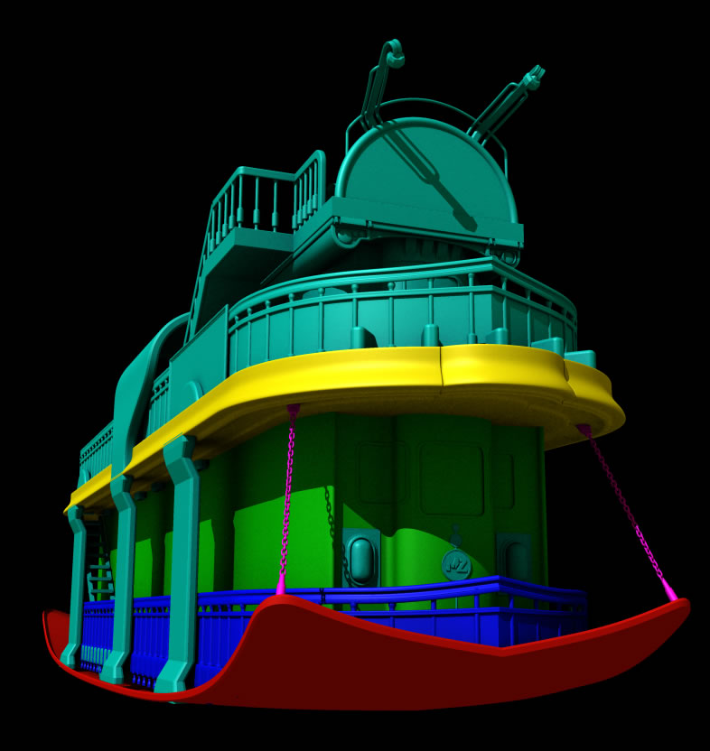
For my first example I will take the model of the building on the left. Some elements of this mode are left out compared to original model from the picture, to make things simpler. I have rendered one image with that model. It is divided by colors so it can be easier to explain what I am talking about. Just click on the image to get the full size.
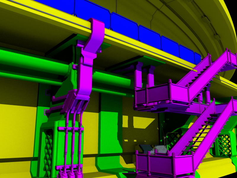 |
example 1 - left building model |
So let's start to examine this model step by step. First, we will start with the yellow part since it is the main structure on which every other details are built. The yellow part was made with simple use of extrude tool which extrudes profile curve along the path curve.
Example:
First you have to draw a profile curve. I usually switch to front view for this. Then go to the Create > CP Curve Tool - click on the box for options and select 1 Linear. Now draw the curve similiar to the one that I did below. Remember, these curves that I use for examples are not the real ones used in my picture ... they only show the way I did stuff.

Now that we have the profile curve we will create the path curve on which the profile will be extruded. To create path curve, I didn't use the CP Curve Tool as you probably supposed ... I have done things a little bit different. What I did, was that I created the perfect circle, detached a little part of it and then scaled that small part and deleted the rest of the circle.
Go to the Create > Nurbs Primitives > Circle. This creates the circle at the middle of the scene. What I have done is that I scaled it a little bit and selected two curve points like on the picture below. Then I went to the Edit Curves > Detach Curves, which divided the curves on two part based on the points that I previously selected. After that I erased the large part and I left the smaller one.
I have also scaled the path curve (part of the circle) so that it is proportional to the profile curve. Like in the picture. At this moment, one of the things you need to watch out is the pivot point of the profile curve because extrude tool use this information. It is best to align it similiar to the pivot point in the picture below.

After I have done all my preparations, I have selected these two curves. It is important to first select profile curve and then the path curve. Then I went to the Surfaces > Extrude - click on little box and in the extrude options menu set the Result position to At Path, Pivot to Component and Orientation to Profile Normal. Also check that all other options are set to the default values. Click Extrude and that's it. The main structure in the model on the left of the image is here:
As you can see, it was easy to do this, just a few clicks and that's it. One more important thing ... I recommend to do this in separate scene/file and later when it is finished you just import it to the original scene where you blocked the image.
Now the green structure that holds the yellow one.
The big pipes are made in similiar way as the object above. I created one Nurbs circle, and I have used the same path curve as the one above but a little bit scaled up. This is easy to do, so I will not explain this through the images. The stuff that I will show you is the model that holds the pipes and on which magenta stuff are attached. Let's see these few simpe steps to get similiar shapes.
First thing that I have done is that I created the profile curve. As before I have used the CP Curve Tool which was set to linear (option menu in case you forgot). I just draw the profile curve as in picture below. This curve should be closed. I have used the linear curve to get the strong sharp edges ... which is what I want for this model.

After I created the profile curve I selected it and jumped to Surfaces > Bevel Plus options. In options menu I set Bevel Width and Depth to 0.1, Extrude distance 0.8, Outer Bevel style to Convex Crease and Inner Bevel Style to the same as Outer. Also in Output options I have used: Polygons, Tessel Method to Sampling, Sampling to 1 and Samples 6. After you click Bevel you should get something like object in the picture below:
We still need to get a hole in the bottom part. This is where that grid will be. First thing I did is that I have used Edit Polygons > Split Polygon Tool. This is very usefull tool and believe me you will use it a lot when it comes to poly modelling. After the tool selection, click on the edges like I did in the picture below and press enter or right mouse button to finish it.
After I made the separate polygon in the bottom part of this structure, I went to polygon selection mode, selected this polygon and done the extrusion (Edit Polygons > Extrude Face) three times. First time I just scaled down the polygon so that I get thicker edge. Then for the second extrusion I also scaled it down, but just a little bit and moved it a little bit inside. The second extrusion was made to get the smoother edge.
After I did the third Extrude of the polygon, I have just pushed it somewhere near other edge (picture below). Don't worry about the precision here, because one half of this object will soon be deleted.
But before you delete the half of the object we need to cut it in half. For this I switched to side view then I went to the options of the Edit Polygons > Cut Faces Tool. In the option menu of this tool check the Delete the Cut Faces and enter the cut tool. Now (in front view) we have to draw a vertical cut line that goes somewhere through the middle of this object. The way you cut it, is crucial. If you do it from bottom to top then the right part of cutted object will be deleted which is what we want. Also, make sure that you keep the SHIFT key pressed to get the straight line going from bottom to top. After I did my cut, I have got the object from picture below. One more thing that I did is that I have set the pivot point to the inner edge. I hope that you know how to do this since this is a basic stuff.
To get the simetrical left part, you just have to duplicate this part and scale it -1 in Z direction. This simple step produced the object below, but...
... they are still separated and we want them to become one. No problem ... just select both parts and jump to Polygons > Combine. The two objects have becomed one ... but they are still not fully conected. ;) The middle part of them has Vertices that are not merged together, and they should be. To do this go to the Edit Polygons > Merge Vertices options and in options menu set Distance to something small like 0.001. If you set it to a higher value some vertices that are not supposed to merge, will merge together, so in that situation you can mess up the model, and because of that be carefull with this value, especially when the history is off. ;) So, as you can see it on the picture below, the basic model is finished.
Now let me show you how to do a simple grid in this hole that we have created. ;)
First, switch to the front view, create the cylinder (Create > Polygon Primitives > Cylinder). After you have created the cylinder, scale it and move to the position like in the picture below (not the green one but the blue one). Also make sure that you have rotated it... I have set it to 45 degrees. Now select that pipe, duplicate it (Ctrl+D) and move it in negative y direction ... this step is shown in picture below...
After you did the first duplicate you can do the repeated duplicate with Shift+D. As you will see, the duplicate with shift pressed on replicates the first duplication and transformation. Just do this several times until there are enough cylinders to cover the hole, like in picture below.
Now the other side. Just select all of the cylinders that you have created, group them together (Ctrl+G), duplicate the (standard way ... Ctrl+D) and set scale in X direction to -1 to get the mirror effect. After you have done this, you will probably want to duplicate few cyilinders at the bottom to fill up the grid completely.
It's time to get rid of the parts we don't need. Guess what ... we will use Cut Tool again. ;) But first you have to select all of the cylinders and combine them together in one mesh so we can cut it in just few passes and keep them as one object. So select all of them and Polygons > Combine. Now go to the Edit Polygons > Cut Faces tool > options and make sure that Delete the cut faces is checked. Now cut the combined mesh like I did in the picture below.
After the cut, select the object and align the pivot to the center of it so you can manipulate it easier. With object selected select Modify > Center Pivot. Now move the grid to the position you want, and in this example I made another copy for the other end. Picture shows it all. ;)
At this moment you can also group the grid and the main element together (Ctrl+G), maybe do another Center Pivot after the group, and position it to the position you want. I have modified a little bit the structure (yellow one) that we did in first steps so that this new model fits better.
For the other parts of this structure on the left, I will not go through the whole process of modeling ... I will just mention in few sentences how I did these objects. So for example, the magenta stuff in the picture below was not too hard to do. I have used similar tools like in the previous parts. The process always goes in similar ways. For some parts I have created the profile curve, then Bevel Plus and duplicated this part few times. For the pipes I have used the cylinder and extrude-move-scale it few times to get the shape. There are also some simple primitive objects, like torus .... they are used at the position where pipe gets into the object below.
In this example I have also used a lot of cylinders which were moved, scaled and edited a little bit to fit the fence model. There are also simple poly plane objects between these cylinders... on which we will apply simple but good looking texture in texturing section. As you can see, on top of every vertical cylinder in the fence lies one poly sphere. Yes, these details look simple when you zoom in closely, but it is a small part in the final picture so why not cut time. ;) The models that hold up the fence are also created from profile curves using bevel plus tool.
Now comes the fence from above (picture below). For this I will show you the few steps which I have used to make it in few minutes. As you can see, the fence is repeatable... so you just need to do the first model and then duplicate it.
Let's see a simple example of this in picture below. The model is separated a little bit just to show you what it is made of. The pipes on the top are made with the extrude tool. The path and profile curve are below. For profile curve I have created one nurbs circle and for the path curve I have used CP Curve Tool but this time set to degree 3 named cubic. The parts on the left and right are simple cylinders and spheres and the big flat part where grid will be (simulated using textures) is made by lofting the two path curves for the pipe on the top and bottom. The loft tool is Surfaces > Loft .. you just need to select two curves and click on this.
Now let's get back to the initial model. We don't need the vertical cylinder on the right side since we will duplicate the whole object. But first make sure that everything is grouped together and that the pivot point is set to the position like in picture below.
Back to the scene from above. Go to the top view and position this part of the fence in its initial position. Be sure to rotate it to the right angle so that the fence follows the direction of the structure. Use the edges of that structure as the reference when rotating the fence from top.
Next step was to make duplicates. Do this from the top ... then after you do a duplicate of the fence part, move it and rotate as in picture below. Now...
...keep doing the duplicates until you get the full fence. You can try to do the duplicate with transform (shift+D) ... but you need to get the right rotation after the first duplicate that you have made, or you can do it by just duplicating it and moving, rotating, then again... ;) Well, that's it about the fence. It was a simple step, wasn't it?
That's it for that left part of the image...
Transport Venichle:
We are not finished with modeling. ;) So, for the second part of the modeling I will show you how I did the transport ship-bus. Parts of this model were made with NURBS and other with polygons. For example the yellow element in the picture below are made with three NURBS surfaces, while the chains are made with polys. If you are doing stuff with polygons then you know what teseelations will look like, while when you are working with NURBS you have to set tesselation manually for every surface. There is also the other way ... and that's to let the MentalRay use global tesselassion for every object in scene. Just in case you want to try this it is under the Window > Rendering Editors > Render Globals then in mentalray menu go to the Overrides > Tesselation and click the checkbox on the left of Surface Approx. Now get back to model.
Yellow part - top floor
First the yellow part of this model (image above). It is a simple nurbs object made with simple path curve and revolve, but let's go step by step...
First you have to draw profile curve like the one in the picture below. As you can see, I did that in front view, and in the centre of the scene ... in this way the pivot will be aligned to the center of the scene. The curve is made with, as usual, CP Curve Tool with 3 Cubic degree.
We will use this curve with revolve tool to get the shape suitable for the front of the ship. But just in case, check that pivot point is positioned at the end point of the bottom part of the curve since the curve will revolve around this axis. Now, with curve selected go to the Surfaces > Revolve box-options. In the options menu only set the End Sweep Angle to 180. Also make sure that the other options are set to default values. In case they are not, in options of revolve tool go to the Edit > Reset Settings which will reset the values to default, and then set the End Sweep Angle. Click Revolve and you will get this:
We still have to tweak few things to get the shape like in the initial model. But, we have to do one step before the CV's tweaking. Why? Because if we went to tweak the few CVs in the front side of this model, since the surface is tangency smooth, we will not get the sharp transitions like in the colored picture from above. Because of that, we will break the tangent continuity in two isoparms and then tweak the CVs to get the desirable shape. Select the two isoparm as in picture below and then Edit Nurbs > Surface Editing > Break Tangent.
At the first sight nothing happens, but there is one difference ... we have some new rows of CVs. Now, let's move that CVs in the right position. Go to the top view ... switch to the wireframe view mode and select the CVs like in picture below.
Now move them forward (Z) until you are satisfied, and then to get the more circular shape deselect the left and right rows of CVs and move the middle part a little bit more in Z direction. The shape that you want and need, is the one like in picture below.
This is the time to duplicate this object. Then scale it in to -1 in Z direction so that you get the mirror, and also move it in Z direction to the place where you want the end of the ship to be. After you did that, select the two isoparm like in picture below...
... and do a loft (Surfaces > Loft). Then do this for the other side, and there it is. If your Construction History is set to on, then you can still move the ends of this model in Z directions and new loft will be created momentarily as you drag the ends. What you can still do to make things more compact, is to combine these parts together in one object. So select front side, then the left side (picture below) and go to the Edit NURBS > Attach Surfaces options. In options menu set the Connect, Keep, and uncheck Keep Original. After you make the Attach, objects will become one. Some problems may occur when doing this ... like when you do the attach the wrong sides get attached together. These can be solved in several ways but best of them is to select the isoparm of the first object which will get attached and then do this for the second object too. This way the Maya knows which isoparms of first object needs to be attached to the isoparm of second object, and everyone will be satisfied at the end. ;)
Green part - the body
Main part of vehichle model is the green part. As always, a simple object but when combined with others it builds up a nice model. The tools used in this part are similiar to the ones we already used (profile curve, extrude), but there are some new ones like project curve and trim tool. Let's check how these things work.
First I started with the profile curve which I will extrude in y direction. This time I will not use the path curve for extrusion since we don't need it. You just have to draw a curve like in picture below (CP Curve Tool), but just draw the half of the curve. Then make a copy of that part, scale it in X direction to -1 to make a mirror and then do the Edit Curves > Attach Curve Options with Connect and Remove options. You can also uncheck the Keep original since you won't need the original curves. Anyway, at the end it should look like this:
Now select this curve and go to the Surfaces > Extrude Options. In option menu set the Style to Distance, Direction to Specify and Direction Vector to Y. Other options should be set to default values, but you know how to do that already. After you click extrude the curve will make a surface similiar to this one, which is what we want:
If the default extrusion of 1 unit is not sufficent, you can increase that in the Channel Box on the right ... but you need to have history. Now let's create the windows. As always you have to draw a curves. Switch to front view ... but ... the front side of this vehichle is on the other side and when you switch to front view we can not see it. Well, in viewport go to the View > Predefined Bookmarks > Back and guess what ... we have the view from the other side on which we can easily draw and project the curve. Now draw the curve with the CP Curve Tool like I did in the picture below (green - left curve) but do not close it (check my curve). Once you draw it go to the Edit Curves > Open/Close Curves and the curve will be closed.
Now select that curve, make a copy of it and scale it in X direction to -1 so that we get a mirror copy. After that make another copy, do a Modify > Center Pivot and move it do the middle of the object and scale it a little bit in x direction .... like in picture below
It is time to use a tool which we haven't mentioned before ... the project curve on surface tool which you can find under the Edit Nurbs menu. But let's see how can this tool be of any help to us. First check that you are in the front or back view ... then select the three curves and jump to the Edit NURBS > Project Curve On Surface. If the options of this tool are not set to the default values some problems may occur, so check that. What this tool did is that, as the name says, it projected the curves we made onto the extruded surface that we have created. The project curve, with default options, is dependant on the viewport which is focused at the moment so make sure you are in front view or back. Well, the result of this should look like picture below.
When we used the projection tool, the curves were projected at the back and at the front side of our model (pic above), and since we don't need the curves in the back you can select and delete them, bye bye. Now, to cut the windows with the curves projected at the front side we will use the trim tool... again something new. Just select the surface, and jump to Edit NURBS > Trim Tool - options. In the option menu set the Keep ... I think Discard is set by default, but then you would need to select the three window surfaces and with Keep option you only need to select one that you want to keep. So enter the tool, select the surface that you want to keep, like I did in pic below, and press Enter. That's it the windows are here.
It's time to do the rubber edge on the windows. Just create a simple circle (Create > NURBS Primitives > Curves). Then move it and scale it like I did in picture below. This is what we will use as the profile curve. Now, first select the circle, then select the trim edge ... to select this edge click with right mouse button on the model and choose Trim Edge and select the window edge. Then...
... go to the Surfaces > Extrude - options. In options set the values to Tube, At Path, Component and Profile Normal and do the extrusion. Also, do this for other windows and that's it. The glass is left for you to do. ;)
Blue part - the fence.
For the start we will create the half of the circle and move it to the right position. To do this, go to the Create > NURBS Primitives > Circle - options and in options menu set the Sweep Angle to 180 ... and other to default values. When you click create you'll get the half of the circle. Now position this as in the picture below, and then duplicate + scale -1 in Z direction to get the other part which you also have to move to the other end.
Now select both curves and go to the Edit Curves > Attach Curve - options. Set the Connect and Keep and uncheck Keep Original. Click Attach and the curves will be atached on one side. To close the other end go to the Edit Curves > Open/Close Curves - options to close the other end.
We have the path curve, and it is time to create the profile curve. I made the profile curve with standard CP Curve Tool but this time set to linear. As you can see in picture below, I did not close the curve ... this means it's time to call Open/Close Curves again...
As you already learned ... select the profile curve, then the path curve and do the extrusion (Extrude). The options has to be set to usual values ... Tube, At Path, Component, Profile Normal. When you do the extrude, you will get something like this:
To make this object more interesting, we will reshape the front end of it. To do this select the vertical isoparm in the front and then break the tangent to get the sharp edge ,,, Edit NURBS > Surface Editing > Break Tangent. Now select the CVs like in the picture below and move them in the z direction...
... after you have moved all three rows, deselect the rows of CVs on the both sides so that only the center row is in selection ... and again move it a little bit in z and y direction to get the shape as in picture below.
This was the first step in process of making the fence. What's left to do is the vertical pipes that goes all around. This is something that I will leave to you to think about and try to do. I will only mention few tools that I have used to create this. Those are: Revolve + profile curve, Animate > Motion Paths > Attach to Motion path, and at the end Animate > Create Animation Snapshot. So if you didn't use these tools before, check the Maya manual and try to do it. Remember that there are a lot of modelling tricks that can be achieved by using Animate and specially Deform menu in animation module. ;)
Red part - the bottom surface
This time I will go a little bit faster and show only the key stuff in the images. The bottom part is created from the NURBS Plane which was scaled and moved to the position where I want it. Then in the Channel Box at the makeNurbsPlane options set the Patches U to 5 and Patches V to 4. Then select the middle isoparms along width and do the Break Tangent. After that move the CVs to form the shape like in the picture below.
After that, create the curve from the top, but not with CP Curve Tool. Do this with the same trick as we did for the fence ... the four round edges made with 90 degree circles, attached together and at the end closed. Project this curve from the top onto the shape we have created before.

After that trim the surface since we are only interested in the inner part of the surface. Then select the trimmed edge, do the bevel and that's it. ;)
Magenta part - the chains
The part colored with magenta is very small in the picture above, so if you didn't saw it clearly ... see it again. As you saw it you will recognize the chains that connect the top part of the ship with the bottom. Remember the tools I mentioned before when I told you to create the fence by yourself ... the attach to motion path and create animated snapshot. Well this time I will take care of the explanation how to use them. ;) But, first step will be to create the single chain element which will be copied x times to get the complete model.
There is a simple way to create one element of the chain. But first hide up everything .... the easiest way to do this is to create layer which can be switched off and on everytime you want. Now go to the Create > Polygon Primitives > Torus - options. When options menu appears, change the Subdivision Around Axis from default 20 to 18 and change the Section Radius to 0.35. Click create, and you will get the torus that looks like this:
Now you will see the reason for the 18 sections around the cylinder. Go to the vertex selection mode, select the right side of the torus (top view) and move it in X direction like in picture below. There is it .... the chain element. ;) One more thing ... remember to center the pivot point ... Modify > Center Pivot.
Unhide the other elements and scale and move the chain element to the position near the chain start. Mine was pretty big once I unhid the geometry so I had to do a big scale down. Don't worry about the position, you don't have to be precise, you just put it near the start so you can easily select it later.
Now with CP Curve Tool draw the linear curve from the place where you want the chain to start to the place where it ends. I have used the linear curve with two points, but if you want the fall down be free to play with cubic curve. Ok, the curve should be similar to this one:
Back to the chain element. We have to collect some informations about that element. Just select it and see which axis is pointing in the front direction of it and which one is pointing at in the top direction. As we can see in picture below, the red or x is pointing forward while the G or Y is pointing in the top direction. Yes I forgot ... check if you are in Object axis mode in move tool. Just double click on the move tool and select the Object. Because when you are in World mode you will not be able to see the true axis of the object.
Now let's go and attach the chain element to the curve that we have created. So select the element and the curve and jump to the Animate > Motion Paths > Attach to Motion Path - options. This is the place where we need the informations that we have collected before. As you will see in options menu, there are stuff like Front Axis and Up Axis. These are the ones that you have to set to the values from before .... Front to X and Up to Y. Also, change the Time Range from Time Slider which is default to the Start/End and set the Start Time to 1 and End Time to 100. Other options should be set to default values and that's it ... when you click Attach the chain element will be attached to the curve like in picture below ... and it's not only attached, it is animated from 1 to 100 frame. Try to switch to 100 frame and you will see that element has moved to the other end of the curve.
So how can we use the element attached to the curve to make a chain. Well there is one usefull option called Create Animation Snapshot. Select the chain element and go to the options menu of this tool: Animate > Create Animation Snapshoot - options. In the options menu set the Time Range to Start/End, Start Time to 1, End Time to 100 and Increment to 5. Leave the other options to their default values. Click Snapshot and you will get the chain like in picture below.
In case the chain elements are too close or too far to each other, go to the channel box and in Outputs - snapshot change the increment to lower or higher value and then do the update: Animate > Update Motion Trail/Snapshoot. Do this until you get the right distance. There is still one more thing we have to do ... all chain elements lay in same plane, they are flat and unreal. First step to do, to correct this, is to select that chain element that is attached to the curve. You can notice him by moving the time slider and see which one is moving. ;) Now grab him, move to the frame one where he is at the start of chain, and in channel box go to the Inputs - motionPath ... then set the Front Twist to 0 and keyframe this. Now go to the frame 100 and do another keyframe but this time set the value to something like 1440. That value worked for me, but you can play with this to suit your needs. After you did that do another Update Motion Trail/Snapshoot and that's it (picture below).
We are finished with modeling part. Its was not detailed explanation of every element in the scene, but I think you got the feeling of how I do things. The models are one of crucial elements in the picture like this one, so be patient when it comes to modeling.
Let's se what we can do about the lighting .... next slide please. :)
| < PREVIOUS - WORK IN PROGRESS |