| < PREVIOUS - LIGHTING |
Texturing
In this section I will talk about the texturing process/tricks which I have used in my image. The texturing consumes a big part of the scene creation time. As with other tasks, like modeling, you must make many decisions before you start to texture objects. For example how big the resolution will be for the image texture on some object .... since texture image can consume a lot of memory. As you can assume, for the front objects the high resolution textures may be necessary but for the objects in the back we can pass with low resolution texture or maybe with a simple procedural texture. Take a little time to plan this at the begining of texture process.
The other very important part of texturing are UV maps, which, in case you are working with polygonal object, you have to create before you begin painting-texturing process. In case you have the NURBS object, you will have fixed UV coordinates which you can not change, but there is a solution ... the projection maps.
As for my picture, most textures in it are very simple. In many cases I have used blinn or lambert shader as a starting point. I suppose you already know about this type of shaders and how they behave. If you need specular and reflections, like on metal surfaces, then you would probably want to use Blinn shader. I have used Blinn shader on all metal surfaces in my scene ... for example the dark pipes or stairs on the left. The lambert shader was used for the highway, for the walls on the right building, for the pillars that hold the highway, etc. The lambert doesn't have reflections and speculars but it is faster than blinn so in case you don't need these stuff, the lambert is better solution.
The blinn or lambert shader, in their basic form, are not very spectacular looking. They only calculate the illumination on the surface. To make things a little more interesting... for example old looking dirty metal surface, we have to map the channels of these shader with procedural or image maps. Let's see a little example of this. The default blinn shader is on the left while on the right we have the same blinn but with textures connected to color, diffuse, specular color and bump channels.
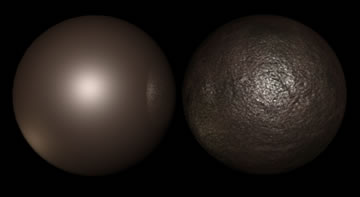
So which one looks more interesting? Left? :) In this simple example I have used few procedural textures like Fractal, Crater, Rock and Marble but in cases where you need greater control over, let's say appearance of color chanell, you would probably use the image texture alone or combined with procedurals.
Combining Procedural and Image maps
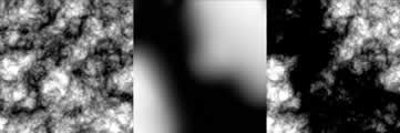
Another important part when it comes to texturing is to learn how to efectively combine procedural textures with image maps. Both of these texturing types have pros and cons. For example procedural textures consume very little memory compared to image maps. The image maps, on the other hand, can be easily controled ... just add details where you need them, while procedurals can be very hard to control. But, there are several ways to combine them. The simplest one will be to blend them together but there are also more sophisticated ways. For example you can use image map to control the appearance of procedural texture by mapping the image map on one of channels in procedural texture. This can be sometimes very usefull since you can have low resolution image map which controls the procedural texture. This way you can get infinite details of the procedural driven by the connected image map. Let me show you the example of this:
The texture on the left is the 3d procedural texture from maya. It is a 2d fractal texture with inflection turned on. The image in the middle is the simple image texture that I have painted in maya (3d Paint Tool). And the last picture is the combined version of these two ... the image was attached to the Threshold channel of the 2d fractal texture:
As I mentioned before... this is a nice way to get a detailed procedural texture controled by the simple painted image. I use this technique from time to time in my scenes. I just wanted to show you this little trick which I will use again in one section below.
Highway Pillars
The highway pillars are one nice and quick example of texturing with images and procedural textures. It has lambert shader which can be saw at the image below. The image is the snapshot from hypershade... I suppose you are familiar with hypershade:
As I said before, since this pillar is made from the material similiar to concrete, I have used the simple lambert shader. The lambert shader was mapped with the procedural color map, the image diffuse map and to simulate the roughness of the surface I have used the bump map with three combined procedural textures plus small mix of image map from diffuse. I can not explain exactly why I have chosen these procedural textures since this comes from practice, but I can show you the result of mixing them together and the way I have used them. It would best to experiment with these textures and learn how they behave when you change their parameters. You have the IPR render for that so don't hesitate a lot ;)
Let's take a look at the diffuse, color and bump layers:
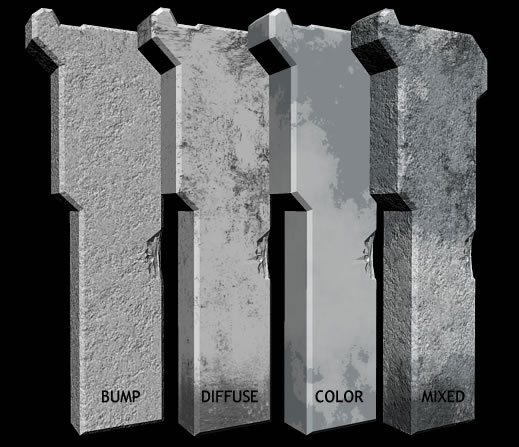
The first three objects are rendered with separate bump, diffuse and color layer and the last one is the result of combining these three layers. As you can see the result looks pretty realistic and combined with good lighting it produces exactly what I want. Now let's examine this shading network a little bit more. We will go layer by layer and step by step. ;) First the bump layer.
Bump layer, as you saw previously in the screenshot of this shading network was produced with the three procedural textures. The textures that I have used were Rock, Marble and Solid fractal. These were all 3d procedural textures which means that they don't need the UV map for them to be mapped correctly. One good side of the 3d textures is that you can easiliy move them through the space and get different texture appearance on the object. This way you can manipulate them to get the chunk you want. Let's see what is happening in the hypershade, starting from roots:
The rock 3D is the first texture ... it lies at the bottom of this shading network. It has the connection to the SolidFractal3D.colorGain. To make connection between them just drag and drop the rock to fractal using midle mouse button. What this does is that the color informations from Rock 3D are used to multiply the values from SolidFractal. Of course, the options of both textures were modified from thir default values. I have spent some time tweaking them to get the right result ... don't think I got it with first shot. ;)
Then there is another procedural texture that is mixed with the previously created SolidFractal. This one is marble (picture below) ... again slightly tweaked to fit my needs. Blend node (blue-red below) was used too, as the name says, to blend these two textures together. There is a slider in the blend options called Blender with which you can change the blend factor of these two. If it is set to 0.5 then it will use 50% of the first and 50% of the second texture to mix them together. In my situation I have set it to 0.7 to use 70% of the second texture (marble) and blend the 30% of the other input which is solidfractal. The blend factor can be mapped with any other floating value .... so if you would have the need to do some more complex textures be free to try to map it with some 2d or 3d textures.
The next connection is to the plus/minus Average node (image below). There is also other connection to this node, and this one comes from the image which was mapped to the diffuse channel. There are few operations that +/- Average node can do, but in this case I did the plus. It simply adds the values from the image texture to the ones generated from the procedural textures. In other words, it raises the proceduraly generated output of blend node with the values from the image file.
And at last the bump connection to the lambert shader. In case you try to drag and drop the +/-A node to the Lambert and select bump, the connection to it will be wrong since the Maya assumes that you want to connect 1d out value to bump. In this case we will create the bump node and connect it manually. This is easy, just create one 2d bump node, and drag the +/-A node on it and click connect. The connection editor will open. In this editor connect the outR or outG ... it doesn't matter which one since we are working in grayscale, and connect it to the bump depth. Now make the connection to the lambert. Drag and drop the bump2d to the lambert ... and in connection editor connect the OutNormal value to the NormalCamera in lambert shader. There is still one thing that you need to do when you have mixed 2d and 3d textures to bump. What you have to do is to turn on Provide3DInfo in attribute editor of bump2d node. You will see that when you turn this on, the 3d textures used to bump up the shader, will become visible.
The next step was to make the color and diffuse channels. These two were very simple. On the color channel I have mapped the marble texture, as shown in the image before. It gives the slightly color variations to the whole texture. Since I have showed the color layer with marble texture before, I will not do it this time, instead I will jump to the diffuse map.
The diffuse map was created using two image textures from my collection. These were mixed together in the Photoshop. The first layer has distributed dirt all around the image while second image was used to get the dirt at the bottom part. It is a usual task to repaint them a little bit. In this situation I have erased some parts of the second layer. The example of these two mixed:

As I mentioned sometime before, to map the image map or 2d texture to the model we need to have the apropriate UV map. Don't try to do the perfect UV map in every situation ... it takes time, and it would be better to spend it on some other tasks. So in this case just select the object and do the Cylindrical map (with default values) around it. You can also try to use planar map, one for the front and one for the side.
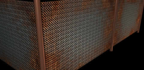
Stairs (transparency mapping)
I wanted the stairs to look like they are all made from metal, and because of that the Blinn shader was apropriate one to choose at the start. Let's look at the stairs from close up just to see the material a little bit better.
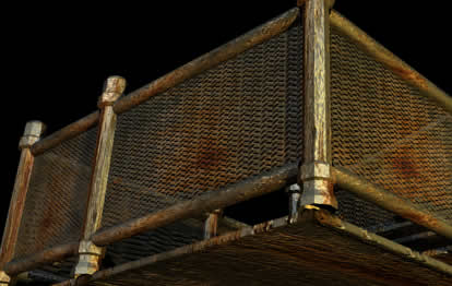
Yes, this object has modeling and texturing flaws, but ... as I was talking before it is far away from camera and pretty dark so why spend time on it when it will look nearly the same as it does now. ;) The simplest way to get the fence grid like from picture above is to map the transparency channel with some image file. In this case I have used the simple element which was repeated many times to get a look that I wanted. The image I have used to map the transparency was this one:
As you can see, it is simple black and white image. What's special about this texture is that it is seamless which means it can be repeated ten or whatever times (in place2dtexture node) and you won't see the seam between them. Now, if you connect the file node to the transparency channel of the blinn node and attach it to the object, like this sphere below, you will get the render similar to this one.
![]()
What's wrong with this shader, is that in areas where the specular is visible, the transparency doesn't look as it needs to. So if the surface is so transparent then the specular should only appear at the parts where the transparency is at zero. The first solution would be to use the same texture to tell specular where it should appear and where not. But what if you have to do this for other channels, like reflection, incandenscence. Then you would need to make 3 connections to the other part of shading network to solve this problem. Lucky for us, there is a simpler solution, and that is to pass the color informations from this shader to the surface shader and map the surface shader with transparency. But, the color information from the base shader must be multyplied with the transparency image before we do the connection to the surface shader. This is shown in the picture below...
And the result is just what it needs to be.
![]()
To get apropriate grid appearance we still need to map the color and the bump values. In my picture I have used the image file to map the color value, but let's see what can we do with the procedural textures. I will use simple poly plane with the same texture from above. We won't go step by step through the process of creating the color map ... instead I will show you the result of my little test and the shading network, and I will explain the connections in shading network. So how does it look with color and bump map? ...
And the shading network looks like this (click on image for bigger version):
DOWNLOAD THE SCENE WITH SHADER
I left around ten minutes of my life for this shading network, and I will leave ten more for little explanation. :)
Since we mapped transparency through the surface shader I left this one alone, and focused on the blinn. First thing I did, is that I mapped the diffuse channel with the ramp node. The ramp type in this node was set to Circular and I added a little noise. As you can see from the scene I have used only two grayscale tones since we don't need the color for the diffuse channel. Then I jumped to color channel. This direct connection to color value comes from the blend node which has two connections from procedural textures. The bottom one is simpe ramp texture with the apropriate color values and little noise. The second one is a little bit more complex. This connection comes from the crater node. Simple colors were used for the first and second color channels of crater node while for the last one I made the connection from the solidFractal node which has the remap ramp connected to change the color values of its output values.
The most important connection, in my oppinion, is the connection to the frequency value of crater node. Remeber that the crater node has two frequency channels ... one for color informations and one for out normal. I mapped both of them since I have used the outNormal value of crater to get the bump in the places where the rust appears. As you can see from the image of network, the ramp texture was connected to this values. The ramp was set so that at the places near the edges I get more rust which fades as it moves to the center. One important thing is to set the AlphaGain of this ramp to something larger than 1 .... which in my case was 2.
As for the bump connections ... there are three Values that influence the appearance of the bump.The first one comes from the brownian texture which was used to add little bump noise all over the surface. Second one is the bump that comes from the same texture which I have used to do the transparency. This one is used to minimize the bump height at the adges where it becomes transparent. Try to test this on simple lambert surface to get the feeling what's truly happening. As you can see there are two bump2d nodes which are connected. The connection is outNormal of the first bump node to the normalCamera of the second. Since the crater node is one of the 3d textures which also generates the outNormal then there is no need to connect this through its own bump3d node. Because of that it is directly connected to the normalCamera of bump2d node. As I mentioned before, the provide3dinfo in first bump2d node must be turned on to allow the 3d procedural to bump up the surface.
That's it for this one...
Ambient Occlusion Map
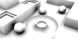
OC map is widely used termin these days. The occlusion map is the best way to make a fast fake simulation of global illumination but without color informations emited and transmited between objects. The renderer, when it calculates occlusion pass does not use material informations about the surrounding objects, only the distances from the point for which it calculates the occ. If the point which it is calculating occ for is surrounded by objects and they are nearby, then the occlusion pass will return some grayscale value. Let's see a little example of this pass.

So how to create the occlusion pass. Well, the occlusion shader does not come as a default shader in mentalray library, so you would probably want to use some third party shader. The one that I have used in this scene was Dirt Map shader from the Daniel Rind. You can find it at his webpage at: http://animus.brinkster.net Just go to the stuff section and DL it. The instructions how to install it comes with it.
Once you have installed the dirtmap shader it will apear in the mentalray Miscellaneous section in hypershade. You can acces this from the drop down Create menu or by the shader menu on the left of hypershade working area. So create it by clicking on it. Once you open it you will see a bunch of options. The Color Base/Dirt, Ray Spread, Near/Far Clip, Samples and Falloff Gain are the most important one in this case and these are the ones I will explain. I will show this using the simple scene just to make things a little bit clearer.
But before I begin with explanation there is one thing to do. The dirt map is not the shader so it can not be directly conected to the objects in the scene. That's why you need to create the Surface Shader (Maya Surface Nodes) and connect the Dirt Map node to the color value of the surfaceShader, like this:
Let's go back to Dirtmap. First the Base Color and Dirt Color. If they are set to default then the base will be white while the dirt will be black. This is what we want most of the time, especially if we will use the dirtmap pass in postprocess. There would be some times when you would want to use the dirt map directly in the scene ... so in such cases you can probably play with these colors ... for example set the base color to something like blue and connect it to the ambient value of lambert shader. But let's stick with black and white for the moment. So leave this values as they are, but be free to play with it. ;)
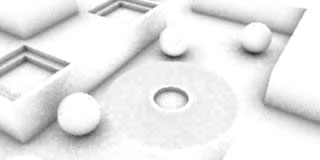
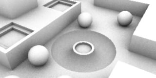
The Ray Spread value is used to set the angle in which the occ pass will collect the information around the shading point. The value you set is maximum angle from the normal vector to the emited ray. I created a little picture (below) to show you visualy what that means. If the value is set to higher value like 90 then all objects that fall between this angle will influence the occlusion value. Of course, if you set it to lower value like 60 then the rays will be shot at lower angle values and some objects that are nearby, but not directly in front of the object, may not contribute to the occ values.
I have also done the two simple renders to show you what I was talking about above.
|
Ray Spread = 90 |
 |
Ray Spread = 60 |
The Near Clip and Far Clip is another interesting value which is worth examining through the images. As the name says, the Near Clip is the distance which, if the occ ray returns it or value below it, will be shaded as the black (DirtColor). If the occlusion ray returns the Far Clip value or some value above it, then it will be shaded as white. Every value that falls within these two will be shaded in some gray tone.
|
Near Clip = 0.1 Far Clip = 10 |
 |
Near Clip = 0.1 Far Clip = 2 |
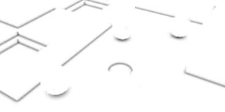 |
Near Clip = 0.05 Far Clip = 0.3 |
The gain value modifies the value returned from the occlusion pass. What it does, is that it raises the value from occ to the power of the value set by gain. Because the occ values always falls between 0 and 1, the effect of the gain value will look like in the picture below.
And in the rendering it will make things more dirty or clear ... similar to changing the Clip values.
|
Fallof = 1 |
|
Fallof = 0.1 |
 |
Fallof = 10 |
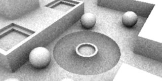
The last but not the least important value is the samples value. As you probably know by increasing the samples you will get the high quality occ but it will take more time to render. In the examples from above I have used the value of 16 which is, as you can see, not enough ... it is still noisy. But, by increasing the values to something like 32 and seting the Min and Max sample level (mentalray render globals) to 0 you will get nice smooth result. Maybe in some cases you would want to increase it... it depends from scene to scene. It is important to set the Min and Max sample level to 0 to tell renderer that it takes one sample per pixel.
 |
Samples = 32 |
The similar values were used for my scene occ pass:
 |
That was all about the texturing part . Now let's see what we can do to optimize rendering a little bit... next slide please. ;)
| < PREVIOUS - LIGHTING |